Bus Pirate is a gadget that talks serial protocols, such as I2C, SPI, etc. You can execute arbitrary transactions or sniff the traffic on the bus. There are legacy versions of the device, like 3 and 4. Their firmware is supported by the community. The newer versions 5 and 6 have a wide support.
Plenty of resources and tutorials about Bus Pirate are available on the web: from Sparkfun, the original pages on the Dangerous Prototypes site, on the website of the newer versions 5 and 6, etc. In this post, I just want to write up a typical sequence of actions for when you hook it up and use it to send a couple I2C commands:
- Just connect the Bus Pirate v3.6 to USB and talk with it using
screenon Linux. - Send some I2C commands at 3.3V level, and without anything connected on the I2C bus, i.e. when a scan of the bus addresses finds no devices.
- Connect a board with the BMP280 sensor chip and read its ID register.
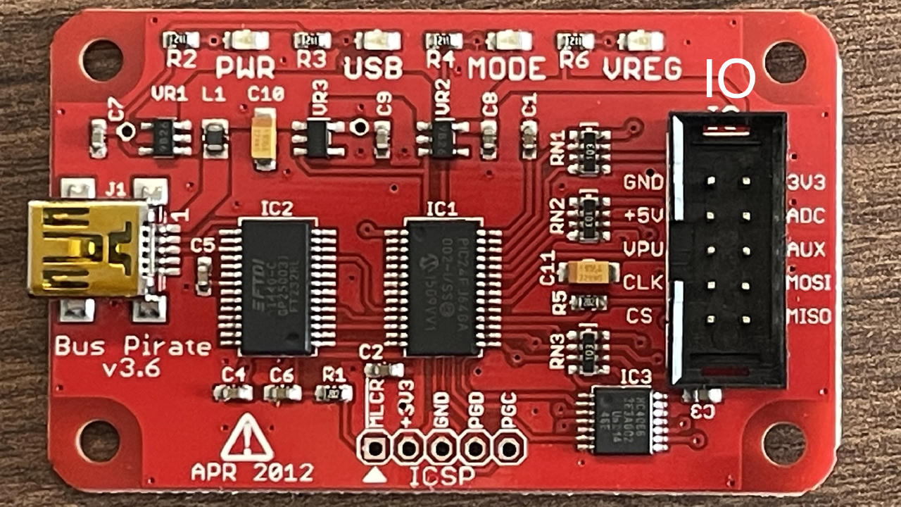
My BusPirate is version v3.6 (the firmware is v5.10 (r559)). Here is its photo:
Talking to Bus Pirate over screen
When you plug a USB cable:
- The red PWR LED on the BusPirate goes on and stays on.
- Other (green) LEDs quickly blink and go off. The “USB” LED also blinks, goes off and stays off. The blinikng shows the activity on the serial connection to Linux.
- Linux also prints to
dmesgthat it found a new USB device, FTDI FT232R USB UART, and says “[the device] is now attached on ttyUSB0”. Indeed, the/dev/ttyUSB0is there.
At this point, Bus Pirate should be available to talk on the serial console.
Let’s use screen for the serial connection.
Launch it with root permissions:
$ sudo screen /dev/ttyUSB0 115200
It shows a blank screen, no prompt.
If there was a prompt line from the device, it was pushed to the serial port
before the screen launched, so there is nothing logged.
But the commands work. Type ? and press Enter to send the command line to the Bus Pirate.
It will reply with a help message that describes available commands:
?
General                                 Protocol interaction
---------------------------------------------------------------------------
?       This help                       (0)     List current macros
=X/|X   Converts X/reverse X            (x)     Macro x
~       Selftest                        [       Start
#       Reset                           ]       Stop
$       Jump to bootloader              {       Start with read
&/%     Delay 1 us/ms                   }       Stop
a/A/@   AUXPIN (low/HI/READ)            "abc"   Send string
b       Set baudrate                    123
c/C     AUX assignment (aux/CS)         0x123
d/D     Measure ADC (once/CONT.)        0b110   Send value
f       Measure frequency               r       Read
g/S     Generate PWM/Servo              /       CLK hi
h       Commandhistory                  \       CLK lo
i       Versioninfo/statusinfo          ^       CLK tick
l/L     Bitorder (msb/LSB)              -       DAT hi
m       Change mode                     _       DAT lo
o       Set output type                 .       DAT read
p/P     Pullup resistors (off/ON)       !       Bit read
s       Script engine                   :       Repeat e.g. r:10
v       Show volts/states               .       Bits to read/write e.g. 0x55.2
w/W     PSU (off/ON)            <x>/<x= >/<0>   Usermacro x/assign x/list all
HiZ>
The i command shows the board information:
HiZ>i
Bus Pirate v3b
Firmware v5.10 (r559)  Bootloader v4.4
DEVID:0x0447 REVID:0x3046 (24FJ64GA002 B8)
http://dangerousprototypes.com
HiZ>
Here, HiZ> is the current “high impedance” mode with no bus communication,
which is default on powerup in this firmware.
Notice, if you forget sudo, screen will abort like this:
$ screen /dev/ttyUSB0 115200
[screen is terminating]
If you see the ? and i commands work, the firmware should be OK for action.
However, it may be needed to flash a newer version:
from the community fork for the Bus Pirate versions 3 and 4,
or the firmware of the new versions 5 and 6.
I did not try to flash anything on Linux yet,
because my current firmware v5.10 (r559) seems to work fine.
Power up the Bus Pirate IO and select 3.3V for the I2C communication
Just to note, to start operating the bus interface, you need to select a bus mode.
The power supply command is W. But:
HiZ>W
Command not used in this mode
HiZ>
Let’s select I2C, as in the Sparkfun tutorial:
HiZ>m
1. HiZ
2. 1-WIRE
3. UART
4. I2C
5. SPI
6. 2WIRE
7. 3WIRE
8. LCD
9. DIO
x. exit(without change)

(1)>4
Set speed:
 1. ~5KHz
 2. ~50KHz
 3. ~100KHz
 4. ~400KHz

(1)>4
Ready
I2C>
Now the green MODE LED is ON.
PSU ON now:
I2C>W
Power supplies ON
I2C>
Now the red VREG LED is ON. And indeed, a multimeter shows that 5V and 3.3V pins are on. All good.
The tutorial goes on to the pull-up resistors:
At this point you might also want to enable pull-up resistors. To do so you need to connect the VPU pin to the correct voltage supply. Then ‘P’ will connect the resistors. The LSM303C Breakout already has pull-up resistors, so we can skip this step. We are ready to start communicating with the IC.
But, in my case, nothing is connected to the bus yet. So, if the VPU pin is not connected and the bus lines are not pulled up, Bus Pirate will notice and warn about it (very nice):
I2C>P
Pull-up resistors ON
Warning: no voltage on Vpullup pin
I2C>
Let’s connect the VPU and the 3.3V pins of the Bus Pirate IO, which will set the 3.3V level for the communication, i.e. CLK and SDA lines.
I2C>P
Pull-up resistors ON
I2C>
- Now
Pdoes not complain. - The CLK and SDA lines jump to 3.3V.
The Bus Pirate is ready for I2C communication at the 3.3V voltage level.
The wiring gets a bit cumbersome: you have to use a breadboard to connect the 3.3V power for the target I2C device and also the VPU pin. And it seems like my BMP280 boards from Pimoroni (very nice 2-6V input) and Az-Delivery (which requires 3.3V, but their wiring diagram on Amazon suggested to connect the power to the 5V pin on Arduino Uno, which burnt two of their handy little boards for me) do not have the pull-up resistors. So, I have to keep the VPU connected to the 3.3 volts.
I2C signals on a scope
Let’s just output some I2C frames and look at the signals on the CLK and SDA lines with a scope. No device is connected to the bus yet.
Bus Pirate provides “macro” i.e. sequences of transactions. The firmware already comes with a couple of them. List available macro:
I2C>(0)
 0.Macro menu
 1.7bit address search
 2.I2C sniffer
I2C>
Excellent macros.
The address scan finds nothing, because nothing is connected yet:
I2C>(1)
Searching I2C address space. Found devices at:


I2C>
A scope capture looks like this, with purple CLK and yellow SDA:
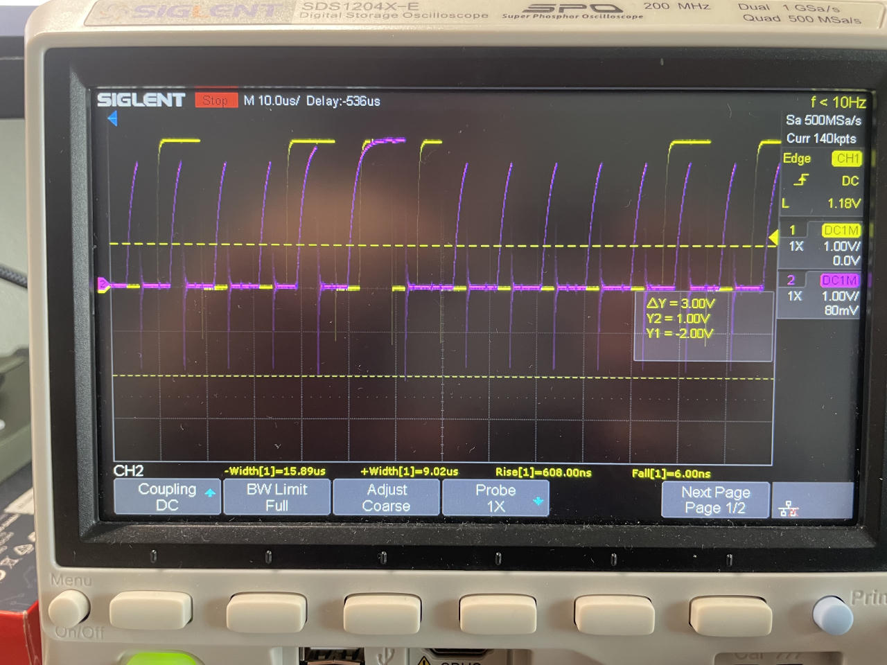
You can see that the clock signal rises up so slowly that the signal does not look square. An I2C device pulls down the line, but the pull up is done by just a resistor. It makes the bus simpler in hardware, but limits its speed. That is the main reason why SPI bus is faster than I2C:
In SPI, devices use push-pull drivers to drive all lines both high and low, which minimizes the time to change the states of the line. The SPI protocol has no maximum speed and speeds in excess of 100 MHz have been achieved.
In I2C, all lines are open-collectors where the device only drives the line low. When the device releases the line, a pull-up resistor pulls the line high. Due to capacitance of the line, it goes to high relatively slow. Because of this, the clock rate must be reduced to allow time for the line to pull high. The I2C protocol has 100 kHz standard speed, 400 kHz fast mode, 1 MHz fast mode plus, 3.4 MHz high speed mode, and 5 MHz ultra-fast mode.
Send a single full I2C transaction
Bus Pirate firmare has this scripting language for the bus commands,
where the bus start condition is [, the end condition is ],
and you can send any bytes in the middle.
For example, let’s get the bus ready and send
a single transaction [ 12 ]:
I2C>W
Power supplies ON
I2C>P
Pull-up resistors ON
I2C>[ 12 ]
I2C START BIT
WRITE: 0x0C NACK
I2C STOP BIT
I2C>
The transaction [ 12 ] looks like this on the scope (CLK is purple, SDA is yellow):
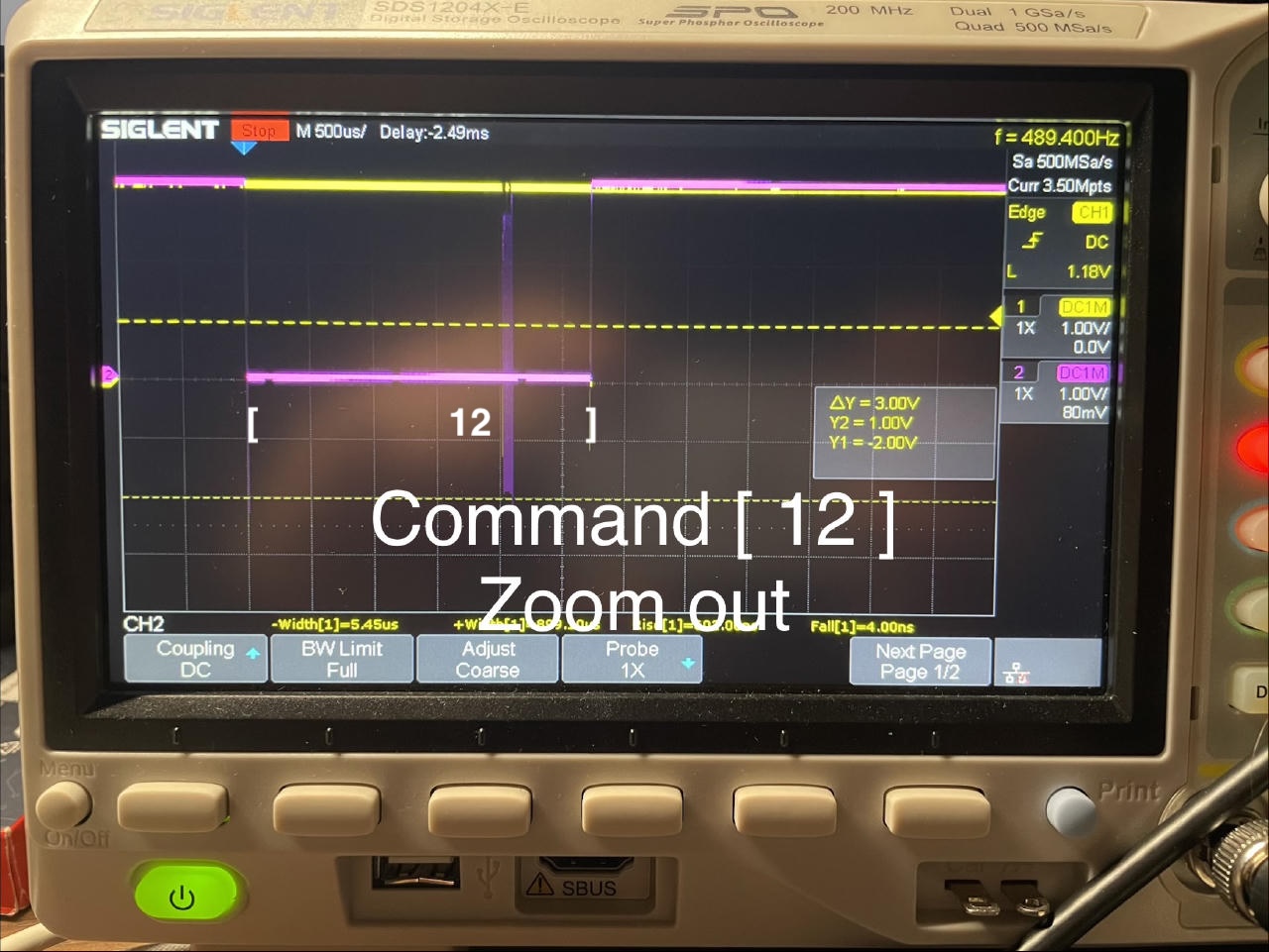
In I2C, when a device controls the bus to send the transaction, it pulls the CLK line down as the bus Start Condition (S), clocks in the data bits on SDA, and releases the bus as the Stop Condition (P).
Talk to a BMP280 barometric sensor
BMP280 is a barometric pressure sensor from Bosch. It can talk SPI or I2C, with an address 0x76 or 0x77. These options are selected by pulling its pins.
I have a Pimoroni (2-6V input) and an Az-Delivery (3.3V only, 5V fries it) boards with this sensor.
It is straightforward how to connect Bus Pirate to these boards for I2C communication: the power pins are GND and 3.3V, the data bus pins are CLK clock and MOSI as the SDA (Serial Data) of the bus. It is a nice feature about I2C: only 4 wires make up the bus, and they have quite straightforward roles.
Of course, the Bus Pirate VPU pin has to be connected to the 3.3V pin as well, to pull up the data pins, as was mentioned above.
After connecting a board, the BMP280 chip shows up in the Bus Pirate I2C address scan like this:
I2C>(0)
 0.Macro menu
 1.7bit address search
 2.I2C sniffer
I2C>
I2C>(1)
Searching I2C address space. Found devices at:
0xEC(0x76 W) 0xED(0x76 R)

I2C>
The command to read the 0xD0 ID register from BMP280 (probably the second r was redundant):
I2C>[ 0xec 0xd0 [  0xed r r ]
I2C START BIT
WRITE: 0xEC ACK
WRITE: 0xD0 ACK
I2C START BIT
WRITE: 0xED ACK
READ: 0x58
READ:  ACK 0x01
NACK
I2C STOP BIT
I2C>
The command structure follows the datasheet “5.2.2 I²C read”:
To be able to read registers, first the register address must be sent in write mode (slave address 111011X0). Then either a stop or a repeated start condition must be generated. After this the slave is addressed in read mode (RW = ‘1’) at address 111011X1, after which the slave sends out data from auto-incremented register addresses until a NOACKM and stop condition occurs. This is depicted in Figure 8 , where two bytes are read from register 0xF6 and 0xF7.
So, the transaction starts with a Start Condition (CLK is pulled down to the ground).
Then the Bus Pirate sends an address byte:
a byte with the 7-bit slave address (0x76 or 0b1110110)
and the RW bit is set to the write mode i.e. = 0: 0b11101100 or 0xEC.
Which is exactly what the Bus Pirate prints in the (1) address scan macro.
The address byte is followed by a control byte.
0xD0 is the BMP280 ID register address.
It is followed by another Start Condition and
the address byte again, but with the mode bit set to read 0xED.
The BMP280 interprets the second Start Condition plus its address byte
as a command to read from its registers,
starting with the register address that is given in the control byte.
The BMP280 chip reads out the values of registers to the bus until a Stop Condition is given.
And the Bus Pirate receives the frames from the sensor chip.
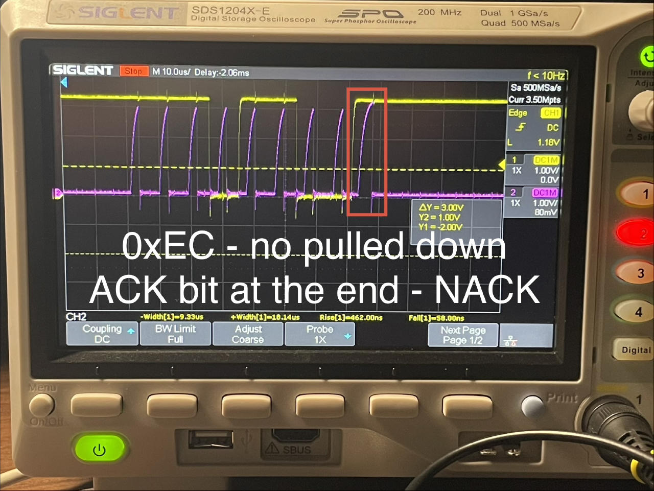
I2C devices signal the reception of a frame by an acknoledgement bit
at the end of the transaction frame, i.e. the 9th bit after the 8 bits of the payload byte.
An I2C device pulls SDA down during the acknowledgement bit,
which indicates that the frame has been received.
A scope capture of such an ACK from the BMP280 to the 0xEC address frame:
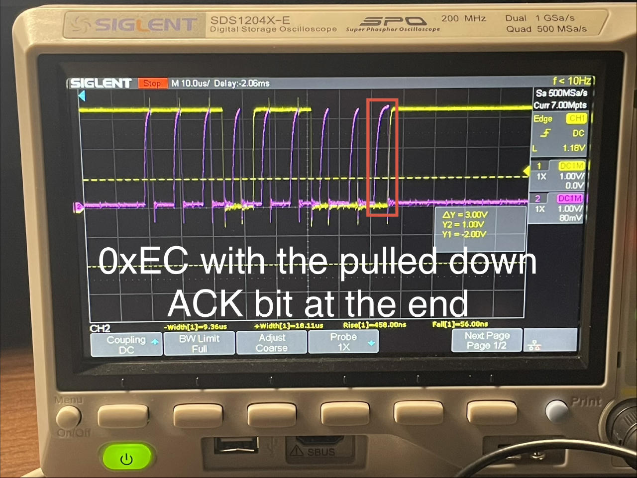
When there is nothing on the bus, the bit is not pulled, and you get a NACK bit:
Conclusion
Bus Pirate is a useful tool. I might come back to it more in future. This post presents a couple quick startup checks and takes a look at some basics of I2C bus.
The Sparkfun tutorial and other resources cover more features of Bus Pirate. And the BMP280 sensor has an excellent datasheet.